ABC Electronic Motor Brake

Stop AC Motor Loads Quickly and Safely...as easy as A-B-C

Electronic braking stops the load by injecting a controlled amount of DC current into a three phase AC motor. The ABC Series "automatic braking controller" features full-wave DC braking which can be adjusted to stop your load quickly, repeatably and reliably...even if load conditions change. The ABC Series meets the three main objectives that are important in every industry: Maximized Safety, Increased Productivity and Maintenance-Free Operation.

Maximum Safety
Protect Machinery & Operators The ABC Series is designed to eliminate dangerous coast-to-stop times of rotating machines and equipment. The ABC Series also eliminates the dangerous practice of jamming the machine to bring it to a stop, which can present potential danger to operators and passers-by alike. OSHA and other safety agencies pay close attention to these types of operating conditions and recognize brakes as an important part of a system to guard against potential dangers. The ABC Series is an ideal way to add braking and eliminate dangerous "coast-to-stop" times in your application.

Increased Productivity
Stop AC Motors Quickly for a Profitable Operation Long coast-to-stop times equal lost production time. Now you don't have to wait forever for the load to come to a stop before you make blade changes or change a tool. Simply stop your equipment using an ABC Series electronic brake for increased efficiency and product through-put. The ABC Series also eliminates any need for "plug reversing." Reversing a load when it is still spinning creates mechanical shock which can cause equipment breakage and extended downtime. Your machinery can now do what it was designed to do... make product at a profit.

Maintenance Free Operation
Eliminate Costly Down Time Using the ABC Series electronic brake eliminates the wear and tear on mechanical brakes in the system. This means less time and money is spent replacing discs or pads (which is especially important given the "shorter life" material used in today's mechanical brakes). Let the mechanical brake act as a holding brake and let the ABC Series do the stopping. The ABC Series eliminates the common (and also dangerous) practice of "jamming" equipment to stop the load. Expensive blades and tooling are no longer "sacrificed" to stop your motor. The ABC Series for faster, smoother stopping and maintenance free operation.

Easy to Install
The ABC Series microprocessor insures proper connections and coordinates system operation. Simply wire the ABC Series electronic brake into the motor starter circuit for a cost effective, maintenance-free means of bringing the motor and load to a stop. No isolation contactors, no additional logic wiring...it works right off the motor input leads! It's as easy as A-B-C.

Easy to Select
The ABC Series units are sized by amperage and should be selected based on the application requirements. "Standard Duty" ratings are sized for 95 - 110% of motor FLA. "Extra Duty" ratings are sized for 150 - 250% of motor FLA. Specify maximum braking current and voltage when ordering.


AC Supply Voltage: 200 - 690 Vac

HP Ratings: 3 to 1000 HP

Amp Ratings: 10 to 1000 Amps

Overload: 500% for 60 sec.

Enclosure: Available as Module Only or in NEMA 1/12

Call us for pricing and availability

    Current Rating
    10 - 1000A in 10 sizes: 10, 24, 50, 100, 200, 300, 400, 550, 800, 1000A

    Voltage Ratings
    Selected voltage ratings + 10%
    Selectable for 50/60Hz + 2 Hz

    Output Capacity
    25% duty cycle at 100% unit rating (model dependant above 200 Amps)

    Inputs
    Starter Monitor = Dry input for auxiliary contact from motor starter.
    Jumper selectable for N.O. or N.C. contact.
    Brake Disable = Dry input for N.O. contact to disable braking before or during operation.
    Can be wired to the starter thermal overload N.O. auxiliary contact to prevent braking of overloaded motor.
    Motor Power Sensor (T3) = voltage input used for sensing motor power presence in sequencing/status circuit and for zero speed sensing during braking.

    Fusing
    Approved for use with existing motor starter fusing when unit is sized for motor FLA. Consult NEC for any other fusing requirements

    Control Method
    Microprocessor unit controls sequencing.
    I/O monitoring and status annunciation.
    Braking current is adjustable via true RMS regulated control using phase angle firing of SCRs.

    Operating Design Temperature
    0 - 50C (32-122F) open, 0 - 40C (32 - 104F) enclosed

    Ambient Conditions
    20 - 95% relative humidity, 0 - 3300ft (1000M) elevation

    Power Circuit
    Full wave bridge, 4 SCRs, designed for use without isolation contactors

    Outputs
    Starter Coil Interlock Two sets of FORM "C" relay contacts for use in interlocking the starter coil and/or other devices to prevent energizing while the braking power is applied.
    Mechanical Brake Release N.O. relay contact for use in controlling electro-mechanical brake as a holding brake.
    When the ABC is"disabled," this circuit controls the mechanical brake normally as if it were the only brake in the system.

    Transient Protection
    RC snubber dv/dt circuit on each SCR device

    Control Circuits
    Self-powered directly from line terminals.
    No separate control voltage required.

    Aux Contact Ratings
    5 amps, 250VAC max

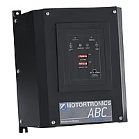
    LED Status Indicators
    Large LEDs: Braking = green; Fault = red
    Small LEDs: Power On, Jog/Armed, Brake Off, Disabled, Over Temp, and Wiring Error

    Operator Adjustments
    Brake Time and Jog Time = 7 position binary dipswitch.
    Brake Current = potentiometer

    Adjustment Ranges
    Brake Jog Times = 0 - 127 seconds in 1 second increments
    Brake Current = Up to 100% unit rating.

    Approvals
    UL, cUL Listed