RX Series
Motor Protection / Overload Relay
Take your motor protection to a new level. Advanced Thermal Modeling software, true motor load monitoring (not just current), power factor, kVA, frequency metering, and a 24h/7-day real-time clock — at an affordable price.
| AC Input Voltage | 200 – 600 VAC |
| Current Rating | Up to 2,000A |
| Real Time Clock | 24h / 7-day programmable |
| Communications | Modbus RTU (RS485) |
| Metering | 3-phase current, voltage, PF, kVA, frequency |
| Overload Classes | Class 5 to 30 |
Thermal Modeling
Tracks all power-related issues contributing to thermal overload using non-volatile memory and real-time clock.
Real-Time Clock
Controls starts/hour, minimum time between starts, backspin timer, and batch process programming.
True Power Metering
Monitors actual motor load — power factor, kVA, and frequency — not just current.
Modbus RTU
RS485 communications for PLC, SCADA, and operator interface integration.
RX Series
Technical Specifications
Type of Load
3-phase AC induction motors
AC Supply Voltage (Motor)
Direct: 200 – 600 VAC, ±10%, 50/60 Hz
With 120V PTs: 690 – 15,000 VAC
Current Range
1 – 2,000 Amps in 3 frame ratings
Service Factor
Programmable from 1.00 to 1.30 for NEMA design motors
Current Measurement
3 window CTs on units up to 75A; external CTs for higher ratings (meets NEC requirements for 3-leg protection)
Power Wiring
Direct feed-through or external CT lead feed-through
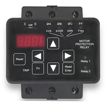
LED Display & Keypad
7-segment, 4-digit alpha-numeric display designed for high ambient light. Full function 4-quadrant navigation keys for easy access to status info and programmable functions.
LED Status Lights
10 LED indicators on the front panel for relay status
Control Voltage
Universal supply: 85 – 265 VAC or DC, 50/60 Hz
Multi-function Digital Input
One (1) dry contact input for Timer Start, Remote Start or Remote Trip
Programmable Output Contacts
1 × Form C (SPDT) 5A, 240VAC max
1 × Form A (SPST) 10A max, ½ HP @ 240VAC
29 programmable trip functions
Event Timer Control
24 hr / 7 day / 7 event timer for automatic start with batch run-time control
Batch Run Timer
Minimum run timer or permissive run timer. Time setting: 1 – 9,999 minutes.
Overload Protection Method
Real-time Motor Thermal Modeling — current sensors + microprocessor continuously calculate motor temperature.
Retentive Thermal Memory
Remembers thermal condition of the motor even with control power loss; thermal register adjusted for off-time when power is restored.
Dual Overload Curves
Two separately programmable curves (start + run). Trip range: Class 5 – 30.
Current Imbalance
Off or 5–30% FLA, 1–20 sec delay
Phase Loss / Sequence
Trips if any phase < 20% FLA. Sequence selectable A-B-C, C-A-B or Off.
Over / Under Voltage
Over: Off or 1–10% of set voltage with 1–20 sec delay
Under (startup): Off or 1–20% with 1–120 sec startup
Under (full speed): Off or 1–20% with 1–20 sec trip delay
Current Trip
Over Current (electronic shear-pin / shock relay): Off or 50–300% FLA, 1–20 sec delay
Under Current (load-loss / loss of prime): Off or 10–90% FLA, 1–60 sec delay
Load & Power Factor Monitor
Load: Off or 20–100% motor kW, 1–20 sec delay
PF: Off or 0.1–1.0 (lead/lag), 1–20 sec delay
Frequency Monitor
Off or 1–10 Hz with 1–20 sec delay
Equipment Ground Fault
Electronic residual current method (no additional CTs). Off or 5–90% of CT, 1–60 sec delay.
Short Circuit / Shorted Load
Peak current quick trip (electronic fuse). Off or 800–1400% FLA, 0.1–0.5 sec delay.
Lockouts & Timers
Restart Delay: 0–999 sec
Starts-per-Hour Lockout: 0–10 starts/hr
Min. Time Between Starts: 1–60 min
Coast-Down Timer: 1–3,600 sec
Metering
Three-phase amps (0–9999A, ±2%), volts (0–600V or 1–15kV, ±2%), kW / kVA / kVAR (or MW / MVA / MVAR), kWh, PF (lead/lag), elapsed time, run cycle counter, remaining thermal capacity.
Packaging & Mounting
Protected Chassis (IP00) with DIN-rail adaptor. Operator interface remotely mountable up to 10 ft (3 m) — NEMA 4/12 mounting kit optional.
Environmental
Altitude: up to 10,000 ft (3,000 m) without derating
Ambient: 0–50°C (32–122°F), 0–95% RH
Approvals
UL, CUL, CE
RX Series
Software Tools
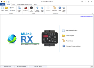
System Requirements
Windows 10 or higher
Intel Core i3 or equivalent
2 GB RAM minimum
100 MB disk space